Table Of Content

You finish the trace by left-clicking again on top of the other pin the airwire connects to. Between the pins, you can left-click as much as you need to "glue" a trace down. EAGLE saves Gerber and PostScript layout files as well as Excellon and Sieb & Meyer drill files. Another UI improvement we like to make in the board editor is turning the grid on.
Step 6: Layout

If the project requires certification, we take this into account at the earliest stages of product development. We prepare documentation for mandatory and voluntary certification in Europe, the USA (FCC, CE, UL, RoHS, and REACH), and other countries. During this time, the team will fix any bugs and defects in the product.
Lee residents bring detailed questions to hearing on PCB landfill design - Berkshire Eagle
Lee residents bring detailed questions to hearing on PCB landfill design.
Posted: Fri, 19 Apr 2024 13:00:00 GMT [source]
Tailored PCB Layout Solutions
There’s no need to worry about disarray during the relocation, as the connections are already in place. Furthermore, you can use the “RATSNEST” feature to tidy up and reestablish connections via the shortest routes between components. A schematic diagram represents the logical representation of an electronic design, displaying the various components in the circuit and how they are connected. You need to add a frame to this view to define the print boundary and display file information. As shown in the image below, in the sidebar of the design software, find ‘ADD’ and use Eagle’s default component library. At the beginning of the project, you need to create a new file.
Routing the Signals
These are just the settings that we've grown accustomed to. In the "Libraries" box is where we'll add a link to the directory where the SparkFun EAGLE libraries are stored. Those limitations still make EAGLE an amazing piece of software. Engineers here at SparkFun could design 99% of our boards using the freeware version, if not for that pesky non-profit stipulation. You still have access to all phases of the EAGLE software, including the Autorouter. This first tutorial goes over how to install the software, and tailor-fit its interface and support files.
PCB Design and Layout Services: Tools Supported
There’s something to love in Autodesk EAGLE for every engineer. In this tutorial, TechSparks will use Eagle to create a circuit board to support a virtual ground circuit, ensuring the reliability and safety of the entire electronic system. In order to proceed with Eagle, it is important to first download a few libraries containing the parts you expect to use in your schematic/circuit. The most important library to download first is the Adafruit GitHub Library. It is a good starting place if you are unsure of what library to use.
Remake It - Autodesk Design & Make - Student Contest
This process is very straightforward, much like creating ‘Word’ or ‘Excel’ documents. It is now finally time to put together the schematic! To do this, go ahead and select the 'addpart' button on the left side of your screen as shown in the first photo.

The download is an executable file; open it and follow the installation instructions. A final length balancing with the MEANDER command provides identical signal lengths.
The Best Free PCB Design Software of 2023 - All3DP
The Best Free PCB Design Software of 2023.
Posted: Mon, 16 Oct 2023 07:00:00 GMT [source]
During the post-warranty period, we can also provide advice on possible modernization and modification of your product. Yes, we carefully select materials and components, trying to find a balance between their quality and price with consideration to the project requirements. All materials we use comply with the EN, IPC, and RoHS international standards. If required, we will use components that comply with the national regulations of your country. After the tests, we finalize the documentation necessary for mass manufacturing, including the bill of materials, Gerber files, etc. If necessary, Integra can also help you choose a manufacturer.
Adding Parts to a Schematic
Opt for the “Properties” option and adjust the “To” and “From” coordinates. It’s advisable to size the box just slightly larger than the space occupied by the components. Finally, go back to the software’s top menu and find ‘Save As…’ in the ‘File’ dropdown options to name and save your project.
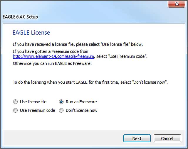
Anytime you want to run Autodesk EAGLE in the future simply pop open your terminal, navigate to the eagle-8.0.0 folder, and enter “./eagle run” to bring up your Control Panel. Linux is the operating system of choice for those wanting complete control over their computing experience. How to use Eagle is what we are going to learn in this entire tutorial series, but to give you a rough idea lets quickly tour into the main aspects of the Eagle software. Remember we will be learning in depth about these in our future tutorials.
That also includes the gerber files, and all EAGLE scripts used in this tutorial. Gerber files -- note the plurality -- each describe single layers of the PCB. One gerber might describe the silkscreen, while another defines where the top copper is. In all, we'll generate seven gerber files to send to the fab house. With those all set, you start a route by left-clicking on a pin where a airwire terminates. The airwire, and connected pins will "glow", and a red or blue line will start on the pin.


No comments:
Post a Comment